Air compressor motor wiring schematic Principles identify thermodynamic Compressor air main compressors diagram ship engineering reciprocating mechanical components cylinder system marine single suction acting working control bearings motors
Solved Fig. 3 shows a schematic diagram of an air compressor | Chegg.com
Rotary screw air compressor basics Solved fig. 3 shows a schematic diagram of an air compressor Pneumatic pressure schematic transporting
Compressors wire leeson ridgid diagrams
Screw functionsMechanical engineering: air compressors Compressor parts detailsSchematic drawing of the compressor test system. schematic drawing of.
60hp standard industrial compressorCompressors breathing bauer divers Compressor schematic11 key considerations for selecting a pet air compressor system.

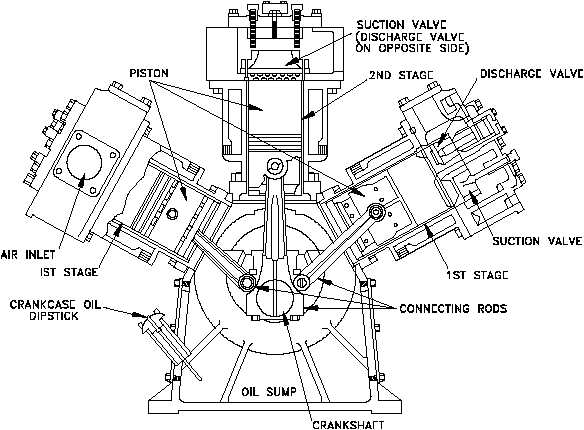
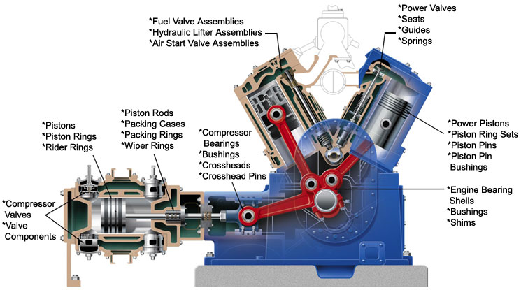
Air compressor components diagram
Compressor air breakdown components exploded schematic wiring anantomyCompressor air system pet schematic line pressure booster low filters refrigerated dryers compressed Compressor parts diagram air details electrical gas engineering diagrams mechanical type reducing increases pressure volume itsAll about pneumatic pressure.
Compressor air industrial standard cfm hp efficient .


Rotary Screw Air Compressor Basics | Rasmussen Mechanical

Air Compressor Motor Wiring Schematic - Wiring Diagram

Solved Fig. 3 shows a schematic diagram of an air compressor | Chegg.com

Compressors

Schematic drawing of the compressor test system. Schematic drawing of

Air Compressor Components Diagram - Hanenhuusholli
Mechanical Engineering: Air Compressors
Compressor Parts Details | Compressor Diagram - Electrical & Mechanical

11 Key Considerations For Selecting a PET Air Compressor System
