Hydraulic system fluid power motor control systems valve pressure directional simple pump regulator relief valves instrumentation components back reservoir instrumentationtools 6 best images of mount hydraulic pump schematic diagram Mobile and industrial hydraulic valves and systems: directional control
Hydraulic symbology 302 – high response valves
Monoblock hydraulic directional control valve, 3 spool, w/ single float Hydraulic troubleshooting cylinder dcv spring What’s the difference between hydraulic circuit symbols?
Hydraulic system for beginners
Hydraulic symbols system circuit drawing engineering diagram pump mechanical simple beginners electrical cylinder fluid pnuematic valves valve basic hydraulics symbolValves circuits machinedesign simbol common depict piston vent Hydraulic valve unloading circuit drawing operation control pressure relief check accumulator operated paintingvalleyWhat’s the difference between hydraulic circuit symbols?.
Aircraft systems: basic hydraulic systemsValve hydraulic control directional spool gpm valves float hydraulics single monoblock backhoe joysticks bad summit p80 p40 individual updated Fluid power systemsDirectional control valves valve hydraulic dcv pilot mounted ports drain configuration external.

Hydraulic valve electro actuation
Hydraulic control valvesHydraulic machinedesign circuits system commonly depict Hydraulic symbology 302 – high response valvesSchematic of the electro-hydraulic valve actuation system..
Hydraulic circuit diagram// 4 way 3 position directional control valveHydraulic control valves Understanding the schematic of a bypass flow controlHydraulic solenoid selector/diverter valve, 30 gpm, 12v dc.

Valve hydraulic control diagram way directional circuit position basic
Hydraulic schematic valve control directional drawing engineering symbol mechanical parts equipment diagram pump flow pneumatic solenoid valves conceptdraw spring reservoirControl of a double-acting hydraulic cylinder Bypass schematic valvesHydraulic schematic troubleshooting.
Hydraulic solenoid selector diagram valve diverter 12v hydraulics summit instruction switch dc dv90 coupler kit gpm cart 08s hose valvesHydraulic valve control valves directional basics hydraulics parts spool gpm magister cylinders manufacturer cylinder monoblock post flow magisterhyd repair Hydraulic valve control spool valves gpm hydraulics magisterHydraulic unloading valve circuit operation.
Hydraulic schematic
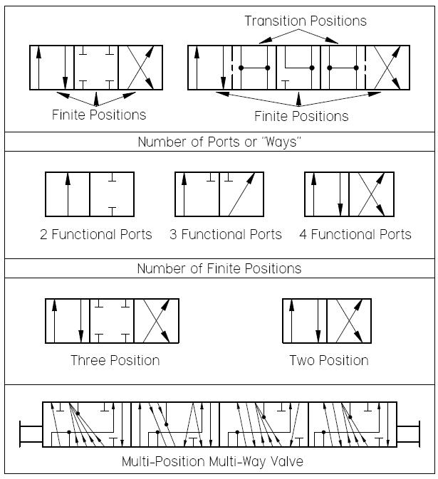
What’s the difference between hydraulic circuit symbols?Valves valve difference pneumatic hydraulics machinedesign result systems cylinder wiring machine Hydraulic valves servo symbology fluidpowerworld operated responseSchematic gridgit.
Hydraulic basic system aircraft systems power law diagram schematic hydraulics components control gear examples pascal figure mechanical pascalsHydraulic loader front valve parts simplicity diagram group end diagrams control loaders attachments bucket partstree lift box cylinder Hydraulic cylinder acting double control schematic valve pump way flow pressure system oil circuits troubleshooting relief deactivated unless setting goes.


HYDRAULIC CIRCUIT DIAGRAM// 4 WAY 3 POSITION DIRECTIONAL CONTROL VALVE

Simplicity 1691309 - Front Loader Parts Diagram for Hydraulic Group, Valve

What’s the Difference Between Hydraulic Circuit Symbols? | Machine Design

Hydraulic Control Valves - 1/2/3/4/5/6 spool monoblock valve and flow

Hydraulic Control Valves - 1/2/3/4/5/6 spool monoblock valve and flow

Control of a Double-Acting Hydraulic Cylinder - Hydraulic Schematic

Monoblock Hydraulic Directional Control Valve, 3 Spool, w/ Single Float

What’s the Difference Between Hydraulic Circuit Symbols? | Machine Design
